The goal of this page is to document the restoration of one ‘ORT Robotic Arm from Concorde Robotique’. Although the rest of my blog in general and an article about this ORT Robotic Arm is in Dutch, I’ve decided to write this particular page in English. The ORT originates from the UK, all internet resources about this robotic arm are in English and I hope to get more responses this way anyway. Please note that this page is a work in progress and gets longer as more results are added. – Rudi
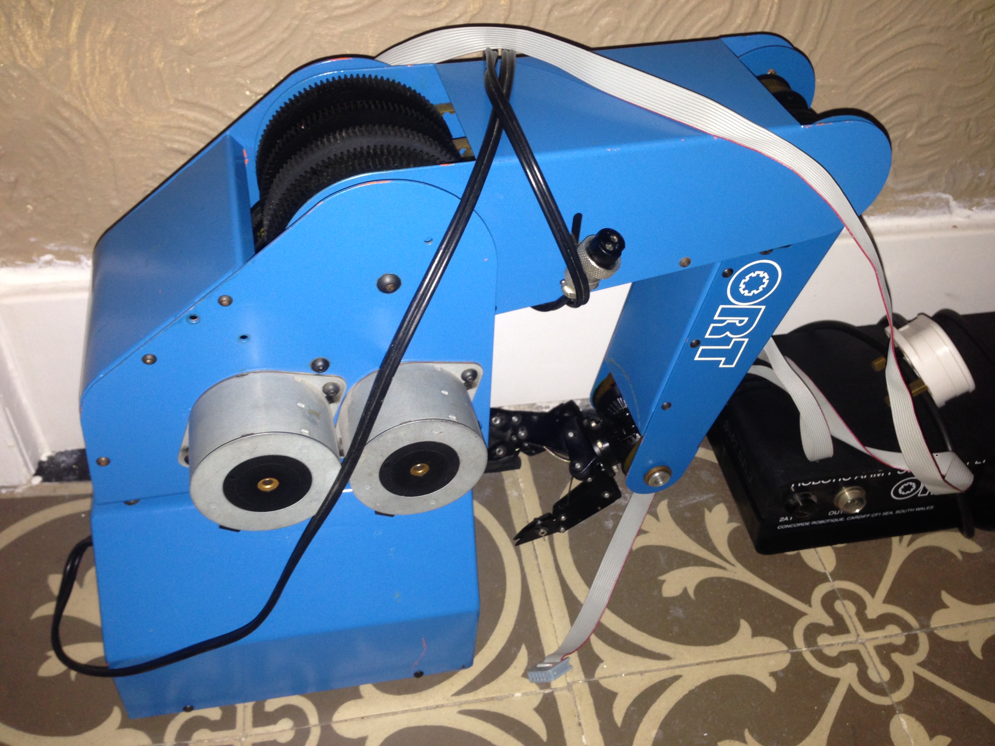
My Concorde Robotice ORT Robotic Arm was produced in 1987 in Cardiff, England. I came across a cheap one in 2013 and could not resist buying it. This robotic arm is in great cosmetic condition. Only the three-finger-gripper looks a bit disorganized but that seems solvable. When moved manually all axes seem to run smoothly. The robotic arm came with a power supply and a 10-wire ribbon cable. Concorde Robotique has zero hits on Google, so this might become an adventure to restore it to full working order.
There are some small scratches on the blue paint, some of them deep enough to reveal a bright orange color: this robotic arm obviously has been factory-repainted. The robotic arm has a quality control sticker from 1987 underneath (‘final test by ORT technical department’). On the inside, only one large printed circuitboard with a handfull of logic chips resides.
As the mechanics look reasonable, I’ve decided to start with the electronics and do the mechanical repairs as I go along. The ORT has 6 unipolar stepper motors, each of which has 6 wires, of which 2 are joined so 5 remain. The wiring goes to a PCB in the base of the arm.The bottom of the base can be removed and the PCB is mounted on top. A permanent power supply wire is fed through the base to a connector on the PCB and a 10-pin header forms the interface with the outside world. There are no switches, so there is no positioning logic to be expected.
I removed the PCB (labeling the stepper motor cables before I removed them) and gave it a good cleaning. How, you might wonder. Easy: I filled the sink with lukewarm water and some dishwashing cleaner, took a soft painting brush and cleaned the whole PCB underwater. I rinsed it afterwards and then let it dry for a couple of hours. Most electronic components can handle water, as long as you keep the electricity away while the board dries. Even the paper quality control sticker survived the beauty treatment!

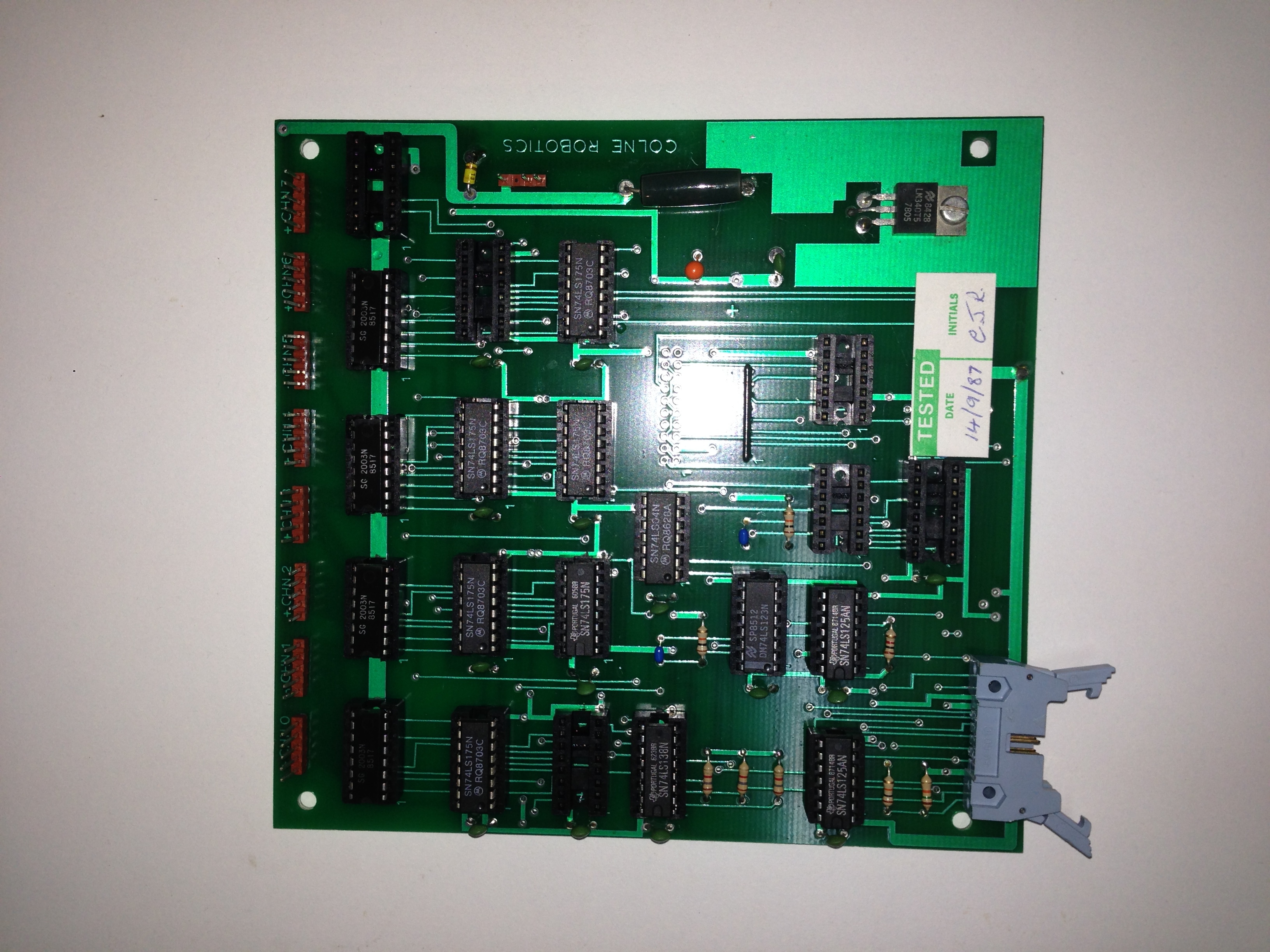
The board has the text ‘COLNE ROBOTICS’ etched in and the sticker says ‘Tested 14/9/87′, which makes the PCB 26 years old. Still in pretty good shape I think! And even better: all chips can be easily replaced. IC’s almost always have their production date stamped on top, usually coded like ‘8305’, which means that IC was produced in week 5 of 1983. The newest chip determines the earliest production date of the board, which in this case is the first week of april in 1987. So this PCB was designed and maybe produced by Colne Robotics and within 4 months after production used by Concorde Robotique. Colne Robotics is a well known name on the internet, they have produced a robotic arm called the Armdroid 1. There is a lot of information about the Armdroid 1 arm available and this Armdroid 1 somewhat resembles the ORT: same gripper, same basic dimensions, same casing and the same orange color the ORT has underneath the blue paint. There are differences though: the ORT has a closed housing and uses timing belt instead of wire.
The PCB has 16 IC’s and 5 empty sockets. On the top side are 8 connectors that have 6 stepper motors connected. These are the IC’s on the board:
- 74LS04 hex inverter (1)
- 74LS123 dual monostable multivibrator with clear (1)
- 74LS125 quad bus buffer negative enable tri-state (2)
- 74LS138 3 to 8 decoder/demultiplexer (1)
- 74LS175 quad d-type flip-flop with clear (6)
- ULN 2003 7 hi-voltage/current darlington transistor (4)
- LM7805 5 V 1 A positive regulator (1)
A 10-pin header is situated in the lower left corner.
As there isn’t anything more evolved on this board than a d-type flip-flop, it stands to reason that the communication is quite low level, i.e. coils of the stepper motors are powered when one of the lines of the 10-pin header is raised. Based on the arrangement of the IC’s, some basic assumptions and a grain of experience, this is my best guess as how this board operates:
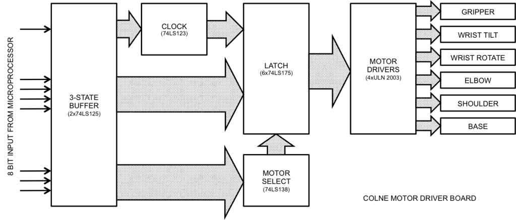
One of the control lines operates as a strobe: a quick negative pulse reads 7 bits into the 3-state buffer. 3 of those bits are decoded into one of 8 lines that select the stepper motor, the other 4 bits represent the stepper motor coil pattern for the selected motor. This pattern is then remembered in the latch, so that afterwards the stepper motor coils keep powered with the pattern. Stepper motors have to be powered with a specific sequence of patterns, for instance 1001, 1100, 0110, 0011, 1001, 1100, etc. This sequence has four patterns, after the fourth pattern the sequence repeats for turning clockwise.
 So, it all bears down on the 10-pin header: what line does what. Documentation is sparse on this subject, so I ohmed the circuit and followed the traces. I’m sure about the +5 V and GND, strobe, select lines and coil lines. But I’m not sure about the specific addressing of either select and coils: I’m afraid that’s going to be trial and error. But I prefer to do that in software, it’s quicker that way.
I mounted the PCB back (made sure it was dry!) and closed the base. Time to put some voltage on the beast!
My 30 Volt 5 Amp laboratory power supply is put to good use, as I don’t trust the included power supply just yet. As I have not checked each IC, there might be a damaged one. In this stage, I’m already happy to have just one axis turning reliably so I can tune out any software and control issues.
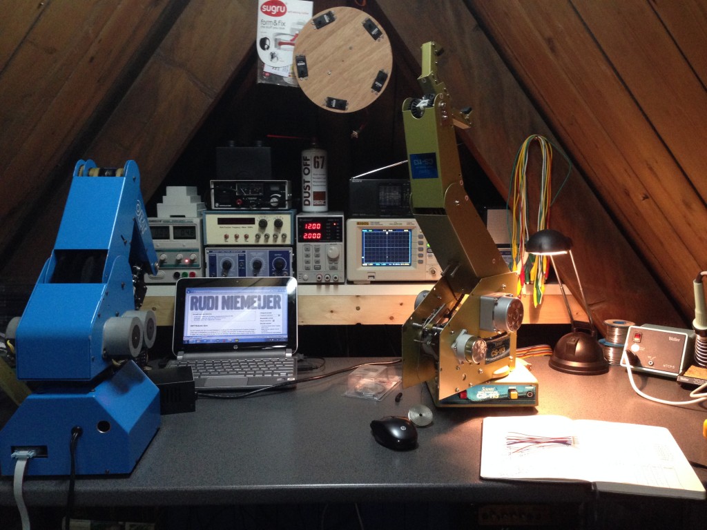
I don’t have a Raspberry Pi at hand like Richard Morris has, but I do have some experience working with Arduino’s. I’m going to use an Arduino to reverse engineer the workings of the 10-pin header interface. As you can imagine, my small electronics workbench is really overflowing at the moment with the arm, the Arduino, a netbook and all sorts of tools, and ah, let’s not forget the other robotic arm I’m restoring, the Sciento CS-113. The restoration of the CS-113 is almost done though.
In order to do easy experimenting, I’ve created a header-to-breadbord converter, that consists of 10 pieces of wire and a spare 10-pin header. I’ve put this converter on a tiny breadboard, which I’ve connected to an Arduino Uno.
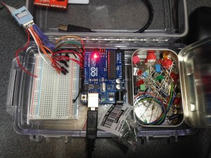
I have a portable Arduino experimenting kit for prototyping hardware, a setup that consists of an Otterbox, a breadboard, an Arduino Uno and an Altoids mint tin with a collection of components and wires. It really helps to have this setup handy, as normally you’re always goofing around with an Arduino because moves so heavily with the wires you connect to it. I’m using it now to get a grip on the 10-pin interface of the ORT.
In the picture to the left you see the converter with purple and orange wires depicting select (orange wires) and motor coils (purple wires). The white wire connects to the strobe pin, black is ground and red is 5 Volt.
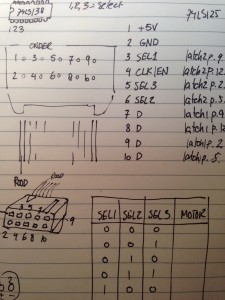
Just to start somewhere, I figured that this must be the pin configuration:
- 5 V
- GND
- Motor select 1
- Strobe
- Motor select 2
- Motor select 3
- Motor coil 1
- Motor coil 2
- Motor coil 3
- Motor coil 4
The motors have the following numbering, as described in the technical documentation of the original 1981 Armdroid from Colne Robotics:
- Gripper – 001
- Wrist pan – 010
- Wrist tilt – 011
- Elbow – 100
- Shoulder – 101
- Base – 110
There are four assumptions to be made, each of them has to be proven right or wrong:
- the strobe line is normally high and has to be set low for a certain amount of time in order to have the circuit read the motor select and motor coil pins;
- the timing for the strobe is somewhere around 1 ms;
- the numbering of the motor select pins correlate with the numbering of the table above;
- the numbering of the motor coils correlates with the numbering of the pins.
An initial test with a random motor selection and four patterns sent in sequence to a motor, experimenting with the timing of the strobe resulted in a turning base motor and a very excited laboratory power supply unit: at 15 V the ORT draws between 1.9 A and 5.5 A!
- Richard Morris is restoring a Colne Robotics Armdroid 1
- Technical documentation about the Colne Robotics Armdroid
- Construction details on the Armdroid
- Lab-Volt Armdroid 1000 brochure
- Alex Zivanovic has a resource page
- Armdroid in september 1981 ETI Magazine (PDF)
- Dan Kohn is working on an Armdroid 1000
- Lab-Volt robotic arms play a game (video)
- William uses an Arduino Mega to test Armdroid motors
hallo,
we zijn bezig met de CS 113 service arm, maar we ondervinden enkele problemen ermee. we hebben een documentatie gevonden erover dat 12V en 5V moeten aan sluiten. we sluiten alles aan met een 2 verschillende voedingen, 1 voor de 5V en 1 voor 12V.
het eerste probleem: we kunnen de ene voeding van 12V nier veder komt dan 10V en dan langs naar omlaag gaat naar 5V en dan gaat ie weer om hoog naar 10V en dat herhaalt de hele tijd. tweede probleem: de onderste servo die niet meer draait, je hoort alleen maar een ratel geluid.
zou u ons hier mee willen helpen, want het is namelijk een project voor school. wilt u ons zo snel mogelijk willen beantwoorden.
met vriendelijke groet,
Michel Postma
Albeda MBO niveau 4 elektrotechiek
Hi Rudi
Is this the best way to contact you ??? please email me back…. have a favor / experiment I’d like you to try with your interface board.
Richard